The 5-Second Trick For Single Cavity Valve Gate Systems
According to this 3rd element of the present creation, a circulation potter's wheel for revolving a cross-sectional unbalanced condition of a laminar flowing material is offered in a hot runner system for providing a laminar moving material. The hot jogger system has (i) an upstream melt passage, (ii) a set of intermediary melt passages downstream from the upstream melt passage, as well as (iii) for at the very least one intermediary melt flow, an associated set of downstream melt flows downstream from the a minimum of one intermediary thaw passage.

BRIEF DESCRIPTION OF THE DRAWINGS For a better understanding of the here and now innovation and also to show more clearly exactly how it might be brought right into effect, referral will now be made using example to the going along with illustrations, revealing write-ups made according to a favored embodiment of today invention, in which: FIG.
1 b, in a schematic profile, shows a warm runner manifold according to the previous art; FIG. 2 is a view on A-A of FIG. 16; FIG. 3, in a sectional sight, shows the melt circulation in a key jogger of the warm runner manifold of FIG. 1 b as it branches right into a set of second runners; FIG.
16; FIG. 5, is a sight on C-C of FIG. 16; FIG (single cavity valve gate systems). 6, in a sectional view, highlights the melt flow of FIG. 4 as the second jogger branches into a pair of tertiary runners; FIG. 7, is a view on D-D on FIG. 1 b; FIG. 8, is a view on E-E of FIG.

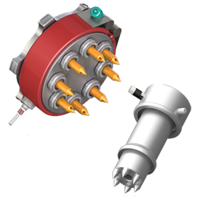
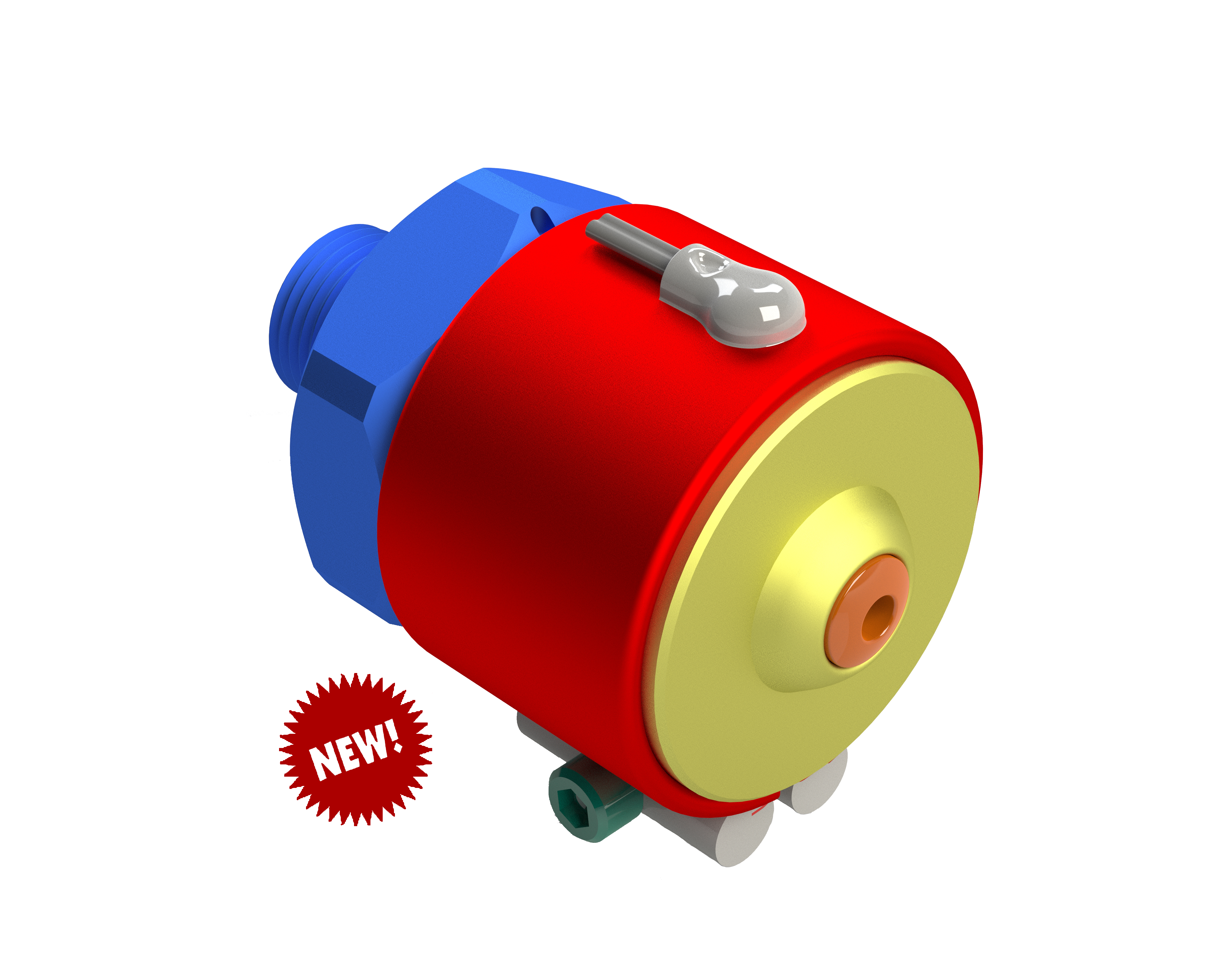
9, is a sectional view on p-p of FIG. 10 a flow-rotating plug based on an embodiment of the invention; FIG. 10, in a perspective sight, highlights the flow-rotating plug of FIG. 8; FIG. 11 a, in a side view, illustrates a part of a stack mold having the plug of FIG.
Unknown Facts About Single Cavity Valve Gate Systems
23; FIG. 25, is a sight on M-M of FIG. 23; FIG. 26, is a sight on N-N of FIG. 23; FIG. 27, is a sight on O-O of FIG. 23; FIG. 28, in a schematic sight, illustrates a hot jogger system incorporating a supporting plug according to a more element of the existing development; FIG.
28; FIG. 30, is a view on M ′-M ′- of FIG. 28; FIG. 31, is a view on N ′-N ′ of FIG. 28; and, FIG. 32, is a sight on O ′-O ′ of FIG. 30. COMPREHENSIVE SUMMARY OF THE INVENTION Referring to FIG. 1 a, there is highlighted in a side sight, a portion of a stack injection molding apparatus 10 according to the previous art.
The smart Trick of Single Cavity Valve Gate Systems That Nobody is Discussing
The jogger system 12 consists of a main jogger 16 for receiving thaw from a melt resource (disappointed). At a very first branch 18, the main runner 16 branches right into two secondary joggers 20. The secondary joggers 20, at particular 2nd branches 22, then branch into tertiary joggers 24. The tertiary runners 24 supply melt to associated nozzles 26, which infuse the melt right into associated mold and mildew tooth cavities (disappointed).
1 b, there is illustrated in a profile, a manifold 14 b of a shot molding device 10 b based on the previous art. The manifold 14 b consists of a jogger system 12 b. The jogger system 12 b consists of a primary runner 16 b for getting melt from a thaw source (not revealed). FIGS. 2-8 are explained relative to the manifold 14 b only for simplicity. Describing FIG. 2, there is highlighted a sectional sight of main runner 16 b at A-A of FIG. 1 b. A warmed outer section 28 of the melt around the jogger wall surface of the key jogger 16 b is shown by shielding.

2, the hotter thaw adjacent the runner wall surface is significantly evenly dispersed concerning the runner wall surface. At the very first branch 18 b, the heated outer section 28 of the circulation is divided into two, as displayed in FIG. 3. Each of these halves of the warmed perimeter then flows right into the second joggers 20 b of the manifold 14 b.
site link important site single cavity valve gate systems